
What is P&ID (Piping and Instrumentation Diagram) – A complete guide
Basic Introduction of Piping and Instrumentation Diagram
A piping and instrumentation diagram (P&ID) is a detailed schematic representation used in process engineering to demonstrate the piping and instrumentation layout of a process flow. It is an important tool in various industries, including chemicals, petrochemicals, pharmaceuticals, power generation and others where complex systems are involved.

P&IDs provide a visual representation of the piping system, including pipes, fittings, valves, and equipment such as sensors, meters, and control circuits. They reflect the interconnection of process equipment and the flow of materials, liquids and gases within a system. In addition, they show how the equipment interacts with the process to control parameters such as pressure, temperature, flow and level.
These diagrams use standardized notation and symbols to communicate information consistently across different engineering disciplines and businesses. Engineers, operators, and maintenance personnel rely on P&IDs for a variety of purposes, including the design, manufacturing, operation, and maintenance of industrial processes. They serve as critical documents for understanding and managing complex systems safely and efficiently throughout their lifecycle.
P&ID can be studied in 3 parts
- Equipment Specification
- Piping Specification
- Instrument Specification
Purpose of P&ID
We can see
- Material Flow
- Piping between various sections including drain and vent line
- Piping components (All valves Size, Class, Tag)
- Mechanical equipment
- Instrumentation
- Heat tracing and insulation details
- Valves and direction of process flow
- Field mounted instruments
- Electrical equipment
We cannot see
- Process information/conditions and physical data
- Operating conditions
- Physical dimension of equipment and location
- Piping details (Pipe routing, length and fittings)
- Support and structural details
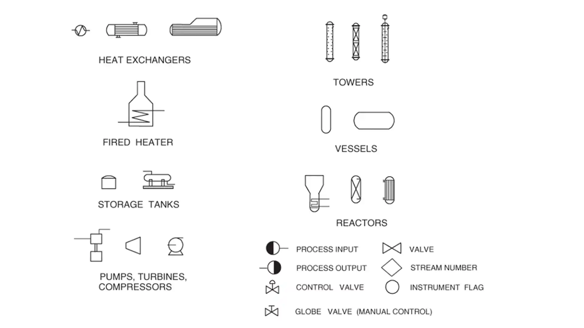
P&ID Symbols
- Equipment Symbol
- Piping Symbol
- Instrument Symbol
Equipment Symbols
Equipment layout
Equipment Identification and numbering
Nozzles
- Equipment Layout (the way something is designed, arranged)
- Shape (Column, Vessel, Tank, Pump)
- Orientation (Horizontal, Vertical, Sloped)
- Relative position (Location relative to other equipment)
- Relative Size (Size relative to other equipment)
2. Equipment Identification
- Look for symbols representing equipment items such as vessels, tanks, pumps, compressors, heat exchangers, reactors, and distillation columns.
- Familiarize yourself with the symbols and their meanings by referring to the legend provided with the P&ID.
- Tag prefix: It shows the type of equipment.
For example – P for Pump, V for Vessel, CT for cooling tower, FL for Filter
- Tag Root Numeric: It shows the typical number to the equipment that is equipment number.
For example – P-101, V-405, CT-203
- Tag Root Alphabetic: When there is more than one equipment is used in single operation then it is given by 1-5 alphabetic letters.
For example – P-101 A and P-101 B, V-405 A and V-405 B
Process Equipment General Format XX-YZZ A/B
- XX are the identification letters for the equipment classification
C -Compressor or Turbine
E -Heat Exchanger
H -Fired Heater
P -Pump
R -Reactor
T -Tower
TK -Storage Tank
V -Vessel
- Y -designates an area within the plant
- ZZ -are the number designation for each item in an equipment class
- A/B -identifies parallel or backup equipment
3. Equipment Nozzles
- Nozzle identification is done by a nozzle box located adjacent to the nozzle that contains unique name (Tag) and size
- Nozzle tag shows for which purpose the nozzle is used
For example: N – Inlet/Outlet, MW – Manway, H – Handhole, L – Level switch
- When there is more than one nozzle used for similar applications, numbers are allocated to nozzles of similar type. Like – N1, N2, N3 used for Nozzles
Piping Symbols
- These symbols vary from company to company and client to client, but only to a certain point. To understand them better, you should always ask or look at legends.
- Types of Line
- Line Identification
- Line continuation
- Piping components
- Piping is shown schematically, in a logical sequence, not as it is actually piped in the field.
- The various piping parts are shown according to following category
- Drains
- Vents
- Reducers
- Valves
- Flush connections
- Steam and Air traps
- Relief device
- Each pipeline will have a label that give a unique identifier, size and piping specification code.
- Note: – Piping length and elevation, isometrics and stress consideration are not shown in p&id.
Types of line connection
- Main line (Pipe Line)
- Process connections
- Pneumatic signals
- Electrical signals
- Data Links
- Capillary Tubing
- Hydraulic signals
- Electromagnetic / sonic signals
Line Identification
Line identification consists of the following information: –
Each line is labelled with the type of fluid, size, Material Code, Area Code, Line specification number, Schedule, Personnel Protection (Insulation), Heat Tracing etc.
- Service designation – Type of fluid flowing through it.
- Numeric number – Pipe line number from the drawing.
- Pipe size – Outer diameter of the pipe.
- Pipe specification code – Pressure Rating & MOC of pipe.
- Insulation and Jacketing – Type of insulation/Jacket
- Line Tracing – Type of tracing (if available)
Line continuation
- In almost all process industry, various materials are transferred to the different parts of the plant. In such case one P&ID sheet is not sufficient to show all piping systems of the material spread in various parts of plant.
- So, we have to continue the pipeline flow in the next sheets also by using line continuation symbol.
- Line continuation symbols show piping connections between different P&IDs.
Piping Components
Piping components consists of: –
- Piping fittings – Flanges, reducers/expanders, spectacle blinds, spacers, strainers etc. along with their size wherever necessary.
- Drains and Vents – are usually indicated using typical symbols along with their size and type (single valve, double valve etc.).
- Flush connection
- Manually operated piping valves – valve type (ball valve, gate valve, check valve etc.), valve size, etc.
- Automated valves – Shutdown valves (SDV), control valves, blowdown valves (BDV) are indicated with size if it is known.
- Safety Devices / Rupture disks
https://youtu.be/7aPi008EeM8
Instrument Symbols
- Instrumentation
Instrumentation is the process of measuring the instruments to monitor and control process.
- Instrument
An instrument is a device that measures a physical quantity such as pressure, temperature, flow, level etc.
- P&ID shows all instruments present over the plant in various processes
- Every instrument is identified and shown both schematically(graphically) and symbolically on the P&ID
Download PDF for Mechanical supervisor and foreman roles and responsibilities Download PDF for Column or Tower maintenance procedure
Piping Question Answer Series Part – 02
Download Free PDF Part-01 Click Here
Read Also
Download Free Piping PDF for Interview Preparation
What is SMAW Welding What is gasket and their types What is a valve and its types?